
"If you can't get free hot water in Marree you are doing something wrong"
|
A Thermal Siphon Solar Hot Water Service
"If you can't get free hot water in Marree you are doing something wrong" |
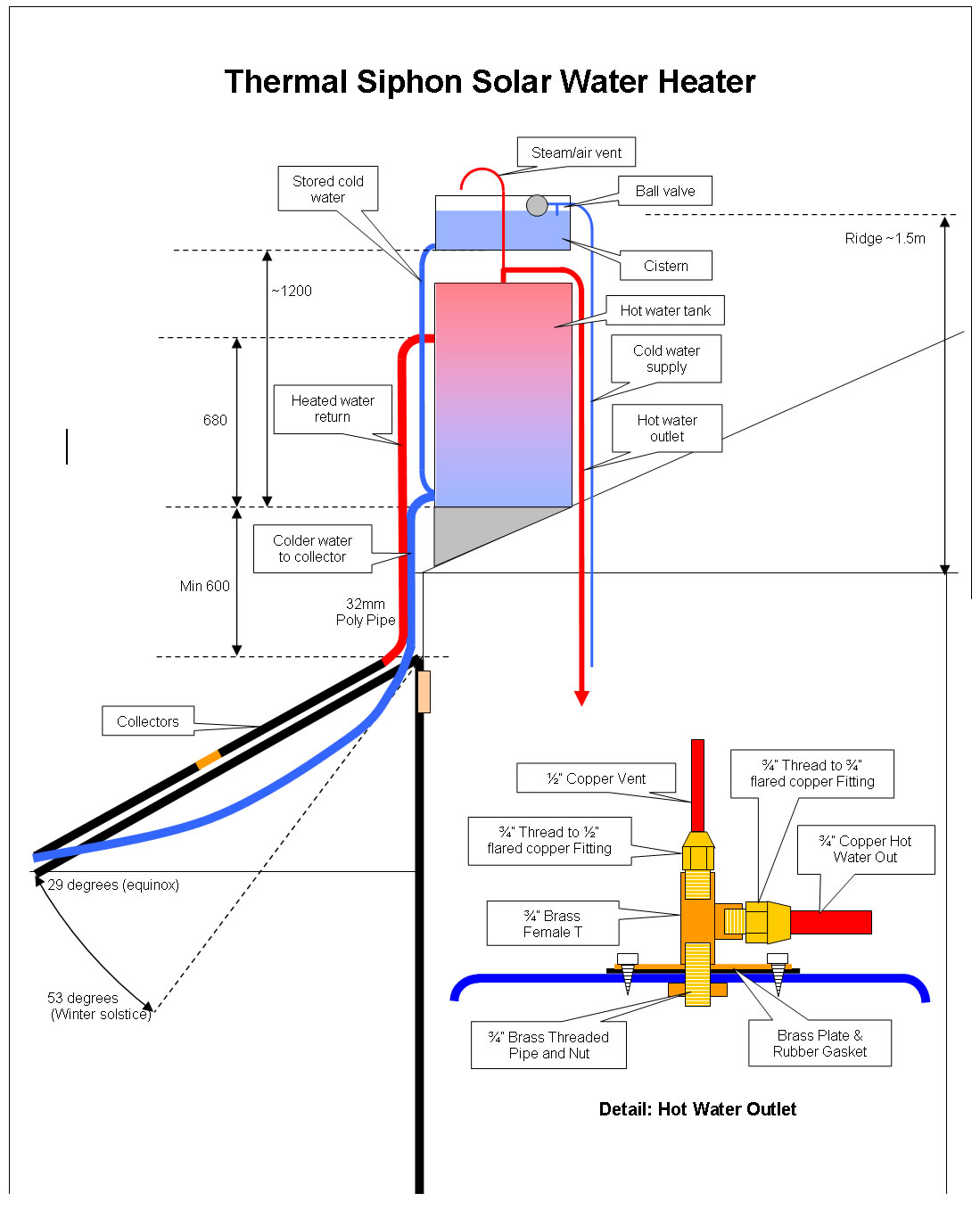 |
Introduction Marree, the home of the Lake Eyre Yacht Club, is in one of the hottest and sunniest areas of Australia. It is also within the boundaries of Australias Great Artesian Basin (GAB) and mineralised artesian bore water is the only town water supply. This water is corrosive and eats out conventional storage hot water services quickly. An all plastic solution to hot water supply should have benefits and so this design was developed around polythene drums and polythene solar collectors. The catch being - is polythene able to withstand the high temperatures of a 50 degree day in Marree? Well, given that the desert is covered in black polypipe for stock watering I'm hoping it is. If the system is still intact after this coming summer it will have passed the heat test. After installation in September it was subject to a few 38 degree days with no problems so it should be OK for seaboard locations Typically we were able to have two very hot showers late afternoon plus dishwashing hot water or two warm to hot showers in the morning. A washing machine could be used in the middle of the day and with typical humidities less than 10%, clothes dry before evening. Currently only half the planned number of collectors are installed as we did not have enough timber to finish the verandah. 500 kms is a long way to go for a hardware store! Search for Thermal Siphon Hot Water in Google for full explanations of how the system works. Basically it uses the principle that hot fluids/gasses rise. The system automatically circulates cold water from the bottom of the tank through the collector -only when the collector is hotter than the cold water - to be stored in the top third, or more, of the tank. The only constraints to this design are it is gravity fed - not mains pressure, and the collectors must be at least 600mm below the bottom of the tank to ensure the thermal siphoning works properly. In our situation this meant installing the tank at the lowest part of the roof to make it as unobtrusive as possible and placing the collectors on a verandah. The tank was placed directly above the shower. All plumbing is installed and serviced at the front of the unit and hidden by a front panel. |
Materials
Polythene drums are available from drum recyclers. The polythene solar collectors were found discarded during a hard rubbish collection. Some panels were holed and thus rejected. If you cannot find polythene collectors many designs for copper pipe based collectors can be found on the Internat.
Construction
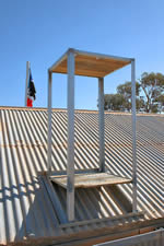 |
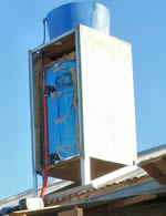
Cabinet The frame is welded galvanised steel angle, although bolts could be used. The frame is 680mm square to allow for the drum to slide between the verticals and to have room for insulation. It is 1.2m between the platforms so that the cistern sits about 300mm above the tank top. The four verticals are 50mm angle with the front ones longer than the rear by the slope of the roof. 30mm angle on all four sides forms the top platform for the cistern. The bottom platform for the tank is framed on the sides and rear only to allow easy installation of plumbing. The platforms are made of secondhand hardwood flooring. The top platform has 50mm holes sawn at the front left corner and the middle front for the cold water cistern pipes and the vent respectively. The bottom platform has a rectangular cut out approximately 50mm deep by 100mm wide on the front left side for the cold and hot water plumbing. The frame is bolted to the base, of 50mm angle, so that the base can be fixed to the roof before the frame is fixed to it. Bend a sheet of cladding to form a wrap around siding for the sides and rear of the frame. This cladding is also bent around the front of the frame about 30mm so the cladding can be fixed from the front. This U shaped cladding is fixed to the frame with self tappers or pop rivets. A cover with 30mm wrap arounds is also made for the front of the unit. This is cut into two parts for above and below the hot water inlet. It is later fixed with self tappers so it can be removed for servicing.
|
Drum Preparation The drum for the hot water tank is prepared before installation: The bungs (check their seals) are screwed down tightly to prevent leaks. Hole saws are used to cut all the holes in the drum. A 90mm hole is drilled in the top of the drum midway between the bungs towards the front of the drum top to allow access to the inside for fitting of the various outlets. This hole is later covered by the Hot Water Outlet Assembly. A hole of 45mm diameter is cut at the bottom of the front wall of the drum for a 32mm tank outlet (cold to collector) and another identically sized hole is cut 2/3 the way up the front of the drum for the other 32mm tank outlet (hot from collector). A hole of diameter required for a 1" tank outlet is also cut 45 degrees to the left of the cold outlet (this fitting points to front left corner of cabinet) at the bottom wall of the drum for the cold water from the cistern. An identical sized hole is cut in the bottom of the cistern wall for this same pipe. A 3/4" hole is cut close to the top of the cistern above the previous hole for the cold water connection to the ball valve in the cistern. All fittings are now installed on the tank and cistern. A length of fencing wire with about 150mm of one end bent over and inserted inside the fitting makes easy work of installation via the inside of the drum. The 32mm tank outlets were filed with a Sureform to fit the inside curve of the drum to improve the seal. All fittings have a rubber seal inside and out and silicon is applied to futher ensure a good seal. The Hot Water Outlet Assembly is also sealed with a rubber gasket and silicon. It is mounted so the hot water outlet points to the front left corner of the cabinet and screwed down with 12 stainless steel self tapping screws.
|
|
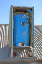 |
Drum Installation The drum is now wrapped in foil insulation and the cabinet lined with the same. Fibreglass insulation was then placed against the rear and side walls of the cabinet and the drum slid in taking care not to dislodge the insulation. |
 |
Cistern and Cold Water Supply The bottom third of a second polythene tank is used as a cistern. It is placed on the top platform and wired to it for stability. The cistern has a ball valve mounted close to the top of the cistern side. The cold water supply is connected to this ball valve via a tap either below the bottom platform of the cabinet or on the wall under the verandah. This tap is turned off for servicing. A 25mm polypipe connects the bottom of the cistern to the bottom of the hot water tank via suitable 1" tank fittings an 90 degree elbows (1" threaded to 25mm polypipe). |
Hot Water Output Assembly Plumbing The hot water outlet is 3/4" copper pipe brought out to a 90 degreee elbow at the front left corner of the cabinet and then down through the hole in the bottom platform to connect to the building hot water supply. A 1/2" copper pipe is connected to the vent outlet and carried through the front centre hole in the top platform and brought up and over the top of the cistern to allow hot air/steam/water to expell into the cistern without splashing outside it. The pipe is kept as close as possible to the cistern top as this determines the final height of the cabinet. |
|
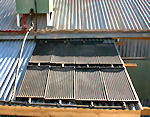 |
Solar Collectors The polythene collectors have mounting points so they can be screwed to the roof. Initially 8 collectors in a 4 x 2 matrix were installed to one side of the tank. In future another set of 8 will be mounted to the other side. Currently the first set of collectors are supplied using 32mm polypipe via a homemade 32mm to 25mm adapter made of two suitable sized copper tubes, one braised inside the other. The adapter is connected to the collectors using the 25mm thin walled polypipe and elbows that they are designed to use. There are a lot of interconnections and T's used with the collectors and although pressure is low I used silicon at each joint to provide a flexible seal. The collector feed pipes should have a continuous grade to the collector as any "humps" in the plumbing will cause airlocks and prevent the siphon effect. When the second set of collectors are installed a new copper adapter in the form of a T will increase the minimum cross sectional area of the feed pipes. This should improve the thermal siphon effect. |
Commissioning Turn on cold water tap and commence filling the tank via the cistern. Check for leaks in the cold water plumbing. As the tank fills any leaks in the solar collector plumbing will become evident. Repair them before continuing the fill. When the tank is full check for leaks in the hot water outlet assembly and plumbing. Finally check the operation of the ball valve as the cistern fills. The water takes about eight hours to heat up to a usable temperature and by the second evening will be as hot as it can get. Enjoy your free shower. |
O:0710 ver1.1 0711