
"Poles apart"
|
Adventure Sailing
Canoe
"Poles apart" |
Mast and Spars
Choosing a Rig
Most outback sailing is done under light wind conditions normally less than 10knots and quite often near still. On the few days were winds reach the brisk sailing conditions often found on Port Phillip Bay it is not worth getting cold and salty – better to go for explore in the surrounding countryside. After perusing the web options I have chosen a “batwing” type sail on a gaff rig sourced from www.friend.ly.net/~dadadata/_Rushton_Bat_Sails.html . I chose the middle design as it is just under twice the area of the American canoe associations sail specification but can easily be reefed to that spec. The batwing design provides a large sail area down low which is ideal for a craft that sails better without heal and allows an easy reduction of %50 of sail with reefing ties. With a gaff rig the mast is short and easily stowed and the sail can be let down easily and cleanly. It requires only one halyard, a downhaul and a main sheet. After trialing the rig I feel a jib (with furling) may be a useful addition for very light winds.
Mast and Spars
Spar information for the batwing sail was sourced from www.friend.ly.net/~dadadata/_Rushton_Bat_Spars.html . The mast was originally 1.6mm aluminium tube 50mmm in diameter – and it bent on the first trip! The second mast will be of 3mm wall thickness - twice as heavy but many times stronger.
The mast shown on Sheet 5 is 3.5m long with a plastic cap in the base and silicon sealed wooden plug with integral halyard pulley at the top. This seals the mast - I try to make sure all components float if separated in a disaster.
The boom and gaff are both 1.6mm wall, 30mm diameter aluminium tube 2.6m long. Each spar has, as shown on the diagram, two saddles. A saddle to tighten the respective edge of the sail and another saddle to help locate the mainsheet in the case of the boom and the halyard for the gaff. The mid-spar saddles are not fixed until the sail is slid over the respective spar as the slots in the sail sleeves will determine location.
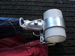 |
Each spar is treated similarly at its junction with the mast and a detail diagram is provided. A strap of 30mm x 4mm Aluminium is is clamped around a 100mm length of 50mm PVC pressure pipe by a bolt which acts as a swivel for the spar. This allows the spar to pivet around the mast without scratching it and swivel up and down as required. |
First measure the circumference of the pipe and mark this length on the alumium with 50mm at each end of it for the swivel end tabs. Drill the end tabs for a 6mm bolt 20mm from the end. The ends are then bent at 90 degrees before the strap is bent around a pipe of about 40mm diameter. Using a smaller diameter pipe and with the "spring" in the metal it will now fit tightly around the 50mm PVC pipe. The ends of the strap are brought together and swivel on a 6mm stainless bolt inserted through the spar end - which is wooden plugged and slotted to suit.
The other end of the spar has a plastic cap which ensures the spars have some buoyancy.
Mast Step
The mast is held in position by the halyard and downhaul. Thus when the sail is lowered the mast can be easily removed. It is supported in the boat by two 40 x 3mm aluminium saddles. The upper saddle is fixed to the front crossmember and the lower saddle is fixed to the mast support bracing. Refer to Sheet 1 for diagram.
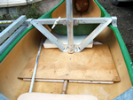 |
The support bracing uses 40mm x 3mm aluminium angle cut and bent to fit between the front crossmember and the plywood floor piece. At its base the bracing is about 150mm wide. The bracing is fixed to the front crossmember with 6mm stainless bolts and to the plywood floor piece with two 6mm countersunk stainless screws. The plywood piece is supported to the height of the stringer by foam sheet (a little more bouyancy) and is screwed to the stringer with three stainless self tapping screws. |
ver1.1 0607