
"Going straight"
|
Adventure Sailing
Canoe
"Going straight" |
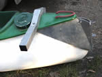
Leeboard and Rudder
The leeboard design was based on the the ACA design at www.enter.net/~skimmer/building/aca_rig.pdf .
Note: An addition has been made to the leeboard design. A vertical 20mm aluminium tube has been placed into a hole drilled into the top aft end of the leeboard to make adjustment easier and safer. I didn't like the idea of putting my fingers through the handle of a leeboard which could rotate any time. The handle hole is still useful when carrying the leeboard. The handle could also provide a point of attachment for a rubber strap that could either help hold the leeboard down when sailing or keep it held up when beached.
The rudder is of similar dimensions to the ACA design but modernized using aluminium cheeks and rubber strap lowering.
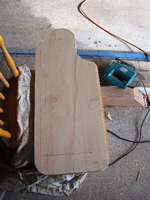
Leeboard and Rudder Woodwork
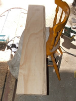
All woodwork is made from one 1.8m x 1.2m sheet of 9.6mm exterior quality ply as per Sheet 2. This material is suitable for situations where the timber is not constantly immersed. Marine ply is exterior ply with mould inhibitors added to prevent rot due to constant immersion and is much more expensive than exterior ply. Three laminations are used for each item with the middle lamination having its grain across the width, rather than the length, to improve strength. Another option would be to use 12.5mm ply and only have two, rather than three, laminations. This would reduce the amount of epoxy used by half as epoxy IS expensive.
Cut all pieces for the rudder and leeboard and laminate them using two part epoxy glue and as many clamps as you can lay your hands on. When laminating the leeboard align all pieces along one long side. The outer pieces will be 10mm narrower on the other side it being the rear, more tapered, edge. Note that the middle lamination is made from two pieces due to sheet size. Mark the shorter piece as the top of the leeboard.
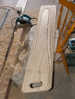
24 hours after glueing refer to the leeboard and rudder drawings and mark them out using ruler and compass. The drawings show the jigsaw/band saw cutting required. Double check all dimensions before cutting and be sure to save the cut off from the rudder that is used as the rudder cheek separator.
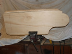
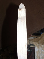
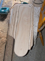
If you are inexperienced in shaping work, especially with an electric planer, practice on scrap first. Try to repeat straight, smooth cuts at the correct angle and a uniform depth. In effect you are graduating your arm action. Set the plane at a comfortable depth – not too much each time, but enough to see what you've done.
The dotted lines are guide lines for planning and should be lightly drawn in soft pencil. Don't forget the bottom taper. Clamp the laminated blank to a flat surface with the edge to be planed overhanging slightly. Use the shaping drawing (on the rudder sheet) as a guide. First plane (much easier if it's an electric plane) to the red line. If you are steady and straight with an electric plane you can count the passes and repeat these on the other surfaces to aid symetry. When satisfied with the red line cut plane the blue cut from half way across the red cut to the next reference mark. A few gentle cuts with the plane across the bottom corners will rough out a transition from edge to bottom taper.
The ply laminations give a good set of “contour lines” to help you plane all surfaces symmetrically and evenly. Repeat the operation for the other five corners (don't forget the bottom taper) to produce a roughly streamlined shape. After completing the planning refine the shape using an orbital sander to produce a smooth curve as shown. Again use the laminations as a guide comparing each side of the rudder/leeboard.
Here are some images of the shaping process:
 |
 |
 |
 |
 |
 |
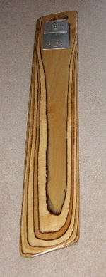
Drill the 12.5mm pivot holes in the rudder and leeboard.
While in woodworking mode make the rudder cheek separator by shaving an equal amount off each end (about 12mm) to fit at the top of the cheeks as shown shaded in the rudder cheek drawing.
The mast support floor may have to be tapered and trimmed to fit your canoe. It fits below the front crossmember on the floor of the canoe to allow the bracing and mast step to be secure. I had to pack with foam sheet (more buoyancy) to bring the floor up to the height of the stringer to which the ply was screwed. A small piece of ply about 200x40mm is used to pack the front of the mast at the upper mast saddle. This compensates for the thickness of the bracing and provides a little rake (backward tilt) to the mast which improves performance.
Finish all items with an overall hand sand to remove sharp edges and varnish with a 50/50 exterior varnish/turpentine mixture. After 24 hours sand with light grade sand paper and re-coat with undiluted varnish, repeating in another 24 hours.
 |
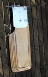
Leeboard Assembly Two pieces of 3mm aluminium are fixed with 4 countersunk screws and silicon on either side of the leeboard pivot point. Use the pivot bolt to help align them and then check for square. The leeboard itself is now complete. The leeboard is located just forward of the “centre of effort” of the sail. COE is determined by mast location (hence sail position) and weight distribution in the canoe. Instructions on finding the COE of a sail are at www.paddlin.com/fivelakes/center_of_effort.html . An incorrectly positioned leeboard can create more “weather helm”, that is more effort is required to hold the rudder in position. As an adventure canoe may have 1 or 2 or 3 crew and assorted gear at different stages of a trip it becomes obvious that a fixed leeboard pivot will never be satisfactory. Hence this design for an adjustable pivot point. Experience will determine the best location for each type of load and the leeboard supports can be calibrated for future reference. The leeboard supports are attached above and below each outrigger crossmember connecting them alongside the canoe. Further detail is in the outrigger section. The combined leeboard fore-aft slide, pivot and fixing fitting is simply constructed from a piece of 3mm aluminium 120x90mm fixed symmetrically to a piece of 40x12 (any width from 12 to 35mm will do) rectangular aluminium tube 100mm long. The fitting is coloured blue in the Leeboard Drawing. Two 6mm bolts 80mm apart (yellow) fix the 3mm plate to the tube. To assemble the leeboard place it (thin edge to the rear!) on the outside of the leeboard supports and pass a 12mm 100mm long bolt and washer through the leeboard, between the leeboard supports and through the fore-aft slide. The entire assembly is held in place by a washer and large wingnut. |
|
Rudder Assembly The rudder cheeks are made from 3mm Aluminium to the dimensions and shape shown in the Rudder Drawing. Four 6.5mm holes and one 12.5mm hole are drilled through both plates at the same time to ensure alignment. One cheek is used to mark out the drilling for the cheek separator that was cut out of the rudder laminate. Two 150mm diameter plastic washers are placed each side of the rudder to reduce friction. These are cut from vinyl plastic or similar material. I used display signs but vinyl book covers would also work. Another three pieces of vinyl are cut using the cheek separator as a pattern. These pieces act as further packing to seperate the cheeks. The third piece ensures that the cheeks are a little further separated than the rudder is thick. They are drilled using the separator as a template. |
The rudder stop, to which the rudder is held by the rubber strap (blue), is simply a 9.6mm diameter aluminium sleeve over a 6mm bolt. It is length is equal to the thickness of the separator plus three thicknesses of the plastic. The tiller bracket is made from 3mm aluminium bent at 120 degrees ensuring the tiller to bracket bolt clears the canoe deck. The bracket is fixed to the starboard side of the rudder cheeks placing the tiller on the opposite side to the outboard. The tiller itself is a length of 20mm plastic electrical conduit. The rudder hinges can be purchased and adapted or alternatively manufactured from 2mm stainless sheet. They are made to fit over the cheeks and tiller bracket. Note that the cheek mounting bolt hole positions are different for the upper and lower hinge. Bend each mount side first then place in vice with hinge lug up and bend it back over vice. The hinge lugs are mounted inside and should end up about 125mm apart. The cheeks are assembled by first bolting the cheek plates and separator ply and plastic together with the centre separator 6mm bolt. The rear tiller bracket is then bolted on followed by the front bracket with the upper rudder hinge over it – both 6mm bolts. The rudder stop spacer is then put into position and the lower rudder hinge fixed using a 6mm bolt through both. The rudder pivot is sleeved using a piece of 1/2" copper water pipe drilled out to 10mm and pressed into the rudder. The plastic friction reducing discs are siliconed on to the rudder and the rudder placed between the cheeks and held with the 10mm rudder pivot bolt. The rudder should pivot freely. Stainless saddles are modified into a U shape
to form each end of the rubber strap connections between the rudder and
cheek. Another saddle is fixed tothe rear top edge of the rudder to attach
the rudder lifter. The rubber strap pulls the rudder down and holds it
against the stop. The lifter pulls the rudder up against the force of the
rubber strap. The lifter cord is brought through a plastic cleat on top
of the cheeks to hold the rudder up when the canoe is pulled up on shore. |
|
 |
Rudder Mounting Bracket A Canadian fiberglass canoe is designed using compound curves so fitting a rudder to the rear of the canoe is difficult. The solution to the most difficult problem of this project is to start with a cardboard template of rough dimensions as per Sheet 2b. Looking at the image of the bracket should be able to make a similar bracket for your canoe. The template needs to reach the outboard mounting bracket bolts as they will hold the rudder bracket to the boat. Note: It is important that the rudder hinge is vertical, or better still has its top mount more aft. If the hinge has its top mount closer to the boat the rudder will tend to fall "in" and at right angles to the boat when left free - thus stalling it. Trim with scissors to fit curves or if the template is too small measure out from edge and make notes on the template nearby. The template does not need the 25mm tab that fits under the coaming of the canoe which is used to bolt it on but don't forget to add it when marking out the aluminium. I usually make a note on the template to remind me. To aid construction the bracket is made as two sides which overlap behind the rudder hinge. The two sides can be bent to the same curve as the canoe in soft 3mm aluminium. As the sides are roughly triangular by placing the hypotenuse together you can make both out of a sheet about 400x350mm.
|
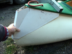 |
The rudder hinge for the bracket is a piece of stainless steel 210x30mm drilled for the pivot rod (a standard 6mm stainless yachting pivot 150mm long. The two 6mm mounting bolts for this hinge also hold the two halves of the bracket together.
The rudder bracket is held onto the boat by the same bolts that hold the outboard bracket. Another bolt clamps the two bracket halves together at the top of the bracket just behind the stern of the canoe.
ver1.2 0708